Project VHD: Introduction to VHDL and VHDL Simulation
This project is a compulsory part of the examination for the
System-on-Chip Design course at the University of Twente. The
goals of this project are:
- To gain practical experience with VHDL (or to refresh the existing
knowledge).
- To become familiar with the Modelsim VHDL simulator.
Modelsim is one of the most powerful VHDL/Verilog simuators that are
currently available. It is a product of Mentor Graphics. The
University of Twente has access to these tools through its membership
of Europractice, an initiative of the European Union
that provides IC design facilities to universities and research
institutes.
The description below refers to various file names. Once you have
logged in, execute the command:
get-module vhd vhd
to get them in a subdirectory vhd. If you lose one of the
files by mistake, you can re-execute this command. Existing files will
not be replaced.
The siso8 circuit that is the topic of this exercise, is
presented in a document entitled VHDL for Synthesis and Simulation (also in "Extra
Materials"). It is strongly recommended to have read that document
before doing any of the exercises.
Exercise VHD-1: Compile and Simulate the copy Architecture of siso8
If you are not yet familiar with Modelsim, study the concise manual (also in "Extra Materials")
especially written for the students of the University of Twente. In
addition, you can consult the tool's help function.
Go to directory vhd that contains the source files, and
launch Modelsim. Then, create there a new Modelsim project. Make sure
that you copy the library settings from the
modelsim.ini file in your current directory (you should do
the same for all future projects that you create for this course!).
Then, add the following files to the project:
- siso8_ent.vhd: the entity declaration of the siso8 circuit.
- siso8_copy_arch.vhd: the description of the copy architecture.
- tb_siso8.vhd: the entities and architectures of the testbench for the siso8 circuit. This file should be compiled with the VHDL 93 option (default).
- conf_tb_siso8_copy.vhd: the configuration declaration that combines the testbench and the copy architecture of siso8 circuit.
Make sure that the order of the files in the project are as given
above and compile them.
Study the file tb_siso8.vhd and pay especially some
attention to the architecture behavior of the entity
tvc_siso8. You should see that the inputs for the simulation
are taken from a file siso8.in that contains a list of input
data. You can modify this file if you want.
Run a simulation and generate waveforms that clearly show that the
circuit functions as intended. In this and all future exercises, it is
important that you are critical on which signals to trace. Do not
blindly include all signals, think of relevant signals in lower levels
of the hierarchy, etc. The choices that you make may affect the grade
that you will receive. The same is true for the formats of the
signals: in some contexts, one prefers to see individual bits, in
others signed or unsigned integers, hexadecimal numbers, etc. Imagine
yourself being the designer and wanting to check the correctness of
your design.
Exercise VHD-2: Compile and Simulate the gcd Architecture
of siso8
Repeat the exercise above for the gcd architecture. In
addition to the files mentioned above, you will now need the following
files:
- siso8_gcd_arch.vhd: the description of the gcd
architecture.
- conf_tb_siso8_gcd.vhd: the configuration declaration that combines the testbench and the copy architecture of siso8 circuit.
First, study the code for the architecture and try to understand the
hardware that is being described. To make things easier, the picture
below shows a block diagram of the hardware.
The emphasis is
on the computations. The logic to compute the req and
ready signals is not included. The signals num1_next
and, respectively, num2_next at the top and bottom of the
diagram are the same signals. Instead of drawing a feedback from
bottom to top, they have been connected by name in order to
reduce clutter in the diagram.
Can you tell which lines of the VHDL code
correspond to to which part of the diagram?
Note: The diagram has been provided as an example for diagrams
that you will be asked to draw. As you can see, when asked to draw a
block diagram, you can use registers, multiplexers and arithmetic
units as the main building blocks.
The picture below is an example of how you could present your
waveforms:
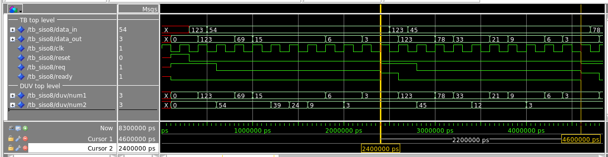
Here are some comments that you can use as guidelines for the waveforms
to be presented by you in your reports for this project and all future
projects:
- The choice of the signals to be displayed is crucial. All relevant
signals should be in the waveforms, but the picture should not be
cluttered with an abundance of less relevant signals. The top-level
signals, I/O signals of entity siso8, which are the internal
signals of the testbench, are obviously relevant. In this case,
num1 and num2 are considered very relevant as well
as they clearly illustrate the progress of Euclid's algorithm: in
every clock cycle one these two signals is changed. In your reports,
motivate shortly why you have chosen to include some signals and omit
others.
- The use of dividers to separate groups of signals can help to
structure the presentation of waveforms.
- Signals are displayed in an appropriate format. In this case, all
numerical values are displayed as "decimal" and not "hexadecimal" as
this makes it easier to follow the calculations.
- Signal names and values are clearly readable. This is related to
the degree of zooming. When zooming out too much Modelsim will not
show all values. It depends on what you want to show whether signal
values should be visible or not.
- The time axis is part of the picture. In this case, it could be a
good idea to use a nanosecond or microsecond resolution instead of
picoseconds; if you change the resolution, make sure to change the
display resolution, not the simulation resolution.
- Two time cursors are used to illustrate the duration of one full
iteration, from the moment that signals req and
ready are raised to the moment that they are raised again.
The distance in time between the cursors helps to see that the
iteration takes 11 clock cycles. In future presentation of waveforms,
use as many time cursors as you consider relevant.
Exercise VHD-3: Block-Based 2-Input-Addition Architecture
for siso8
Design a new architecture
for the siso entity called add2block which, given
input stream i(1), i(2), i(3), etc., produces the output o(2n) =
i(2n-1) + i(2n). There is no valid output o(2n-1), which means that the
ready signal should be '0' for those outputs.
Example: the input stream 45, 8, 23, 19, 12, 34, ... will result in
output stream x, 53, x, 42, x, 46, ... (an x means an output that is
not valid; do not assign any 'X' to data_out; in
general, 'X' should only be used in testbench code, not in
design code).
Before writing any VHDL, first, draw a block diagram as the one
above.
Then, write VHDL that reflects the block diagram. Create an accompanying
VHDL configuration as well. Simulate the design and show that it does
what it is supposed to do.
Note regarding diagrams for this and all future projects:
Hand-drawn diagrams that are clearly readable after photographing and
scanning are acceptable. You can also draw them using any drawing
software of your choice. A PowerPoint file symbols17.ppt to
be found directly under this project's description in the
Modules section of Canvas contains some basic
symbols that you can use for this purpose.
Exercise VHD-4: Pipelined 4-Input-Addition Architecture
for siso8
Design a new architecture
for the siso entity called add4pipe which, given
input stream i(1), i(2), i(3), etc., produces the output o(n) = i(n) +
i(n-1) + i(n-2) + i(n-3), for
n > 3; the output should be invalid for the first 3 inputs.
Example: the input stream 45, 8, 23, 19, 12, 34, ... will result in
output stream x, x, x, 95, 62, 88, ...
Approach the problem in the same way as in VHD-3.
Deliverables
VHD-1 and VHD-2 are for training purposes only. Do not deliver any
report for these exercises.
For VHD-3 and VHD-4,
use the Canvas "file upload" feature to upload the following items
(one upload per team):
- A report in PDF format having at most pages A4, using font sizes
of at least 11pt. For both designs, present your block diagrams
with a short explanation as well as representative waveforms
of your simulations, again with a short explanation.
- All VHDL files created or modified by you (never upload files that
you have not modified). The report should contain a list of all
uploaded VHDL files (for each file: its name and a single-sentence
description). Convert your VHDL files to PDF format using
vhd2pdf before uploading.
Do not forget the VHDL configurations.
Grading
- 3 points can be earned with VHD-3.
- 2 points can be earned with VHD-4.
Remark valid for this and future projects:
Having satisfied
all deliverable requirements is not necessarily a guarantee for the
maximum grade. Some points may be reserved for solutions that are
more ingenious or creative than average, for example.
Last update on:
Thu Feb 9 00:09:04 CET 2023
by Sabih Gerez.